RSL
Refraction


return to main index


Introduction

The tutorial "Reflections using trace() & gather()" provides basic information about the use of the
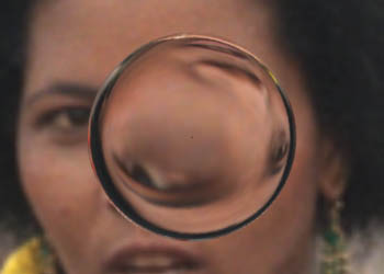
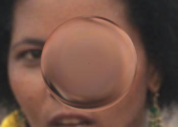
 trace() and gather() functions. Therefore, that material will not be repeated by this tutorial.


Basic Code

The basic code for a shader that calculates raytraced refractions is given in listing 1. Listing 2 is a sample rib document that was used to render a series of images shown in figure 1, 2 and 3.


Figure 1


Figure 2


Figure 3


Listing 1


surface
lens(float  Kd = 0.75,   /* basic brightness */
            Kfrac = 1.5  /* index of refraction */)
{
color   diffusecolor, refractcolor = 1;
normal  n = normalize(N);
vector  i = normalize(I);
vector  nf = faceforward(n, i);
  
/* STEP 1
   Set the apparent surface opacity */
Oi = Os;
  
/* Local copy of the index of refraction */
float ior = Kfrac;
  
/* STEP 2
   If we're shading the front surface divide the
   refractive index of the current material ie. air
   (1.0) by that of the material the ray will enter
   ie. glass (1.5) */
if(-i.n >= 0)
    ior = 1.0/Kfrac;
    
vector refractRay = refract(i, nf, ior);
refractcolor = trace(P, refractRay);
  
/* STEP 3
   Ignore illumination for the moment */
//diffusecolor = Kd * diffuse(nf);
  
/* STEP 4
   Calculate the final apparent surface color */
Ci = Oi * Cs * refractcolor; // * diffusecolor;
}


Listing 2


Option "trace" "int maxdepth" [2]
  
Display "shader_tester" "framebuffer" "rgb"
Format 427 240 1
Projection "perspective" "fov" 40
ShadingRate 1
  
LightSource "distantlight" 1 "intensity" 2.5 
            "from" [0 0 0] "to" [0 0 1]
Translate  0 0 5
Rotate -20 1 0 0
Rotate 0   0 1 0
Scale 1 1 -1
  
WorldBegin
    Attribute "visibility" "trace" [1]
    
    TransformBegin
        Attribute "identifier" "name" ["sphere"]
        Rotate 90 1 0 0
        #Surface "outside_red" "Kd" 0.4
        Surface "lens" "Kd" 0.4 "Kior" 1.5
        AttributeBegin
            Sphere 1 -1 0 70
            Disk 0 1 360
        AttributeEnd
    TransformEnd
    TransformBegin
        Attribute "identifier" "name" ["polygon"]
        Translate 0 -0.05 0
        Scale 30 30 30
        Surface "texmap" "texname" ["swazi.tx"] 
                         "Ks" 0 "Kd" 0.4
        Polygon "P" [-0.5 0 -0.5  -0.5 0 0.5  
                      0.5 0 0.5  0.5 0 -0.5] 
                "st" [0 0  0 1  1 1  1 0]
    TransformEnd
WorldEnd

The "lens" is made from a quadric disk and a hemi-sphere. To raytrace refractions correctly it is very important to ensure the surfaces that define an object face "outwards". For example, figure 4 shows refraction through a lens that has outward facing surfaces. The same lens produced the image shown figure 5 but the disk was incorrectly facing inward.


Figure 4
Correct Refractions


Figure 5
Incorrect Refractions (reversed disk)


Reality Check

An important question to answer is "how realistic are raytraced refractions"? To find out I photographed a sheet of grid paper through a plano-convex lens. The radius of the convex lens surface was 3 inches and its axial thickness was 0.50 inches. The lens was suspended over the paper with its flat surface facing the camera. The distance from the paper to the lens and the paper to the camera were accurately measured. The camera was oriented so that it was perpendicular to the horizontal grid paper.

The "real life" setup was reproduced in a rib file. Figures 6 and 7 show the photograph and the cgi image. For clarity the lens support has been painted-out of the photograph. The refactive index of the lens shader was set to 1.5. Apart from the lack of specular hilites in the cgi version the images match each other very well.


Figure 6
Photograph


Figure 7
CGI Version


© 2002- Malcolm Kesson. All rights reserved.