RSL
|
Creating Fake Lighting Effects
A surface shader generally calculates the apparent color of a surface ( |
|||||
Basic Code
To keep the code developed in this tutorial as simple as possible the
shader shown below does not calculate the true values of the ambient,
diffuse and specular lighting components. Instead, it applies a fake
(diffuse) rim lighting effect based on the angle between the viewing
vector and the surface normal.
Listing 1
Listing 2
|
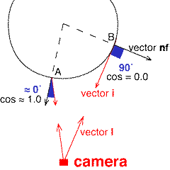
Using the Viewing Vector and Surface NormalThe following illustration shows how the angle between the surface normal and the line-of-sight of the camera ie. the viewing vector, changes from 0.0 degrees at the center of the object (location A) to 90.0 degrees at the rim (location B). |
The apparent brightness of a surface can be based on the way this angle (shown in blue) changes across an object. A convenient method of calculating this angle is via the vector multiplication known as the dot product (also called the scalar or inner product) ie. |
Code Snippet 1
|
|
The snippet of code shown above uses normalized copies of the surface
normal ( |
Code Snippet 2
|
|
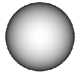
The important point to note is that because the normal used in these calculations has been forced to face the camera, and hence we are only dealing with angles between 0.0 and 90 degrees, the cosines of this range of angles, calculated by the dot product, is in the rangle 0.0 to 1.0. In other words we are applying a fake lighting effect. |
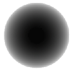
Controlling the Width of the Rim EffectNaturally, the shader should allow an artist to control the width of the rim effect. By providing an instance variable, say, rim_width we can use the smoothstep() function to modify the range of values across a surface. For example, |
Code Snippet 3
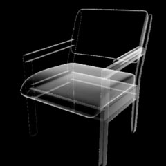
An interesting effect, figure 4, can also be obtained by using the dot product to vary the opacity of a surface rather than its color (snippet 4). Code Snippet 4
Listing 3 provides the full code of a shader that applied the edge effect seen in figure 4. |
|
Listing 3
|
Fake Lighting Direction
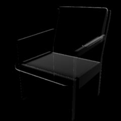
The chair in figure 5 has been rendered using the shader shown
in listing 4. Notice that step 2
consists of two parts. In step 2.1 a uniform
value of |
Listing 4
|
|||
|
© 2002- Malcolm Kesson. All rights reserved.