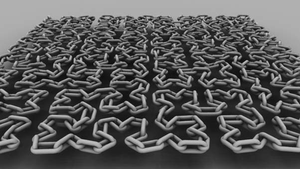
RfM Ribbox
Chain On Curve


return to main index

Revised Jan 2014


Introduction

This tutorial demonstrates how a Ribbox, assigned to a shading group in HyperShade, can generate geometry at render-time. The geometry created by the Ribbox is injected into the output rib stream and as such does not appear in the Maya viewport. For example, figure 1 shows only a curve while figure 2 shows a chain consisting of 700 links generated by a TCL script called by a Ribbox. By querying xyz positions the TCL script was able to distribute links that follow the curve at regular 'u' intervals.

The Hilbert curve was created using the code from the tutorial Hilbert Curve: Mel Implementation


Figure 1


Figure 2


The Scripts

The chain-on-curve "system" consists of two TCL scripts that implement the following procs.

VectorUtils.tcl   (listing 1)
    proc vector { pnt1 pnt2 }
    proc length { vec }
    proc aimY {vec}

ChainUtils.tcl   (listing 2)
    proc chain { OBJNAME numchains hr thick}
    proc linkgen {L ratio thick}

The ChainUtils::linkgen procedure generates a string consisting of two quadric torii, two cylinders and the transformations required to form them into a "link". For example, calling the proc with the following parameter values,
    L 1.0 (link length)
    ratio 0.75 (link length to width ratio)
    thick 0.2 (link thickness)
generates the following block of rib that results in the render shown in figure 3.


AttributeBegin
    Translate 0 0.275 0
    TransformBegin
        Rotate 180.0 0 0 1
        Torus 0.375 0.1 0 360 180.0
    TransformEnd
    TransformBegin
        Translate 0.0 0.5 0.0
        Torus 0.375 0.1 0.0 360 180.0
    TransformEnd
    Rotate -90.0  1 0 0
    TransformBegin
        Translate 0.375 0 0
        Cylinder 0.1 0.0 0.5  360.0
        Translate -0.75 0 0
        Cylinder 0.1 0.0 0.5  360.0
    TransformEnd
AttributeEnd


Figure 3

The VectorUtils::aimY procedure is used to orietate each link so that they "follow" the curve. For more information about aimY refer to,
    Tcl: Align Y-Axis to a Vector, and
    Mel: Align Y Axis to Vector

The main procedure ChainUtils::chain is responsible for stepping along a curve at regular 'u' intervals and placing links at each step.

Listting 1 and 2 should be saved to a directory that is sourced by RenderMan Studio. Suggestions on how this can be done can be found in the tutorial,
    "RfM: Customizing"

The following lines should be added to the users custom RMS.ini file.


set tclDirectory /Users/$USER/Documents/maya/projects/RfM_tcl
# Load the customed TCL procs for use in Ribboxes
LoadExtension tcl [file join $tclDirectory VectorUtils.tcl]
LoadExtension tcl [file join $tclDirectory ChainUtils.tcl]


Listing 1 (ChainUtils.tcl)


# Malcolm Kesson
# 21 October 2012
#
# Workflow
# 1     Create a curve and use mel "rebuildCurve".
# 2     Transform tab, Attribute->RenderMan->Add Custom Shading Group.
# 3  InitialShadingGroup, Attribute->RenderMan->Add Ribbox.
# 4  Ribbox dropdown menu change "None" to "TCL".
# 5  Copy and paste the following command into the Ribbox,
#    don't forget the opening and closing square brackets.
#         [chain $OBJNAME 20 0.5 0.2]
# This will put 20 links along the path of the curve with a link
# width to link length ratio (proportions) of 0.5 and a link 
# thickness of 0.2.
# Revisions:
#   Jan 26 2014 proc now adds links upto a curves max_u value.
proc chain { OBJNAME numchains hr thick} {    
    # In the case of a rebuilt curve u_max will be 1.0, otherwise,
    # is will be a larger value, say, 4.
    set u_max [mel "getAttr $OBJNAME.maxValue"]
    set u_step [expr double($u_max)/($numchains - 0)]    
    
    set rib ""
    set flip 0
    for {set u 0} {$u < $u_max} {set u [expr $u + $u_step] } {
        set next_u [expr $u + $u_step]
        set pnt      [mel "pointOnCurve -pr $u -p $OBJNAME"]
        set next_pnt [mel "pointOnCurve -pr $next_u -p $OBJNAME"]
    
        # Get the transformations to position and orientate a link
        set vec [vector $pnt $next_pnt]
        # The proc "aimY" is implemented in VectorUtils.tcl. Consequently, 
        # VectorUtils.tcl must also be in the same directory as this script.
        set rot [aimY $vec]
        set xrot [lindex $rot 0]
        set zrot [lindex $rot 1]
        set x   [lindex $pnt 0]
        set y   [lindex $pnt 1]
           set z   [lindex $pnt 2]    
        # Link lengths may vary depending on the uniformity of the curve
        set linklen [length $vec]
        
        append rib "AttributeBegin # $u\n"
        append rib "  Identity\n"
        append rib "  Translate $x $y $z\n"
        append rib "  Rotate $zrot 0 0 1\n"
        append rib "  Rotate $xrot 1 0 0\n"
        if {$flip} {
            append rib "  Rotate 90 0 1 0\n"
            set flip 0
        } else {
            set flip 1
            }
        append rib "  [linkgen $linklen $hr $thick]\n"
        append rib "AttributeEnd\n"
        }
    return $rib
    }
  
# This proc is used internally to create a single link constructed
# from two quadric torii and two quadric cylinders.
proc linkgen {L ratio thick} {
    set W [expr $L * $ratio]
    set R [expr double($W) / 2]
    set r [expr double($thick)/2]
    # delta is used to shift the torii to avoid gaps in the chain.
    set delta [expr $R - $r]
    
    # Because the distance between the two torii has been reduced
    # the length of the cylinders must also be reduced.
    set linklen [expr $L - 2.0 * $delta]
    set rib "AttributeBegin\n"
    append rib "    Translate 0 $delta 0\n"
    append rib "    TransformBegin\n"
    append rib "        Rotate 180.0 0 0 1\n"
    append rib "        Torus $R $r 0 360 180.0\n"
    append rib "    TransformEnd\n"
    append rib "    TransformBegin\n"
    append rib "        Translate 0.0 $linklen 0.0\n"
    append rib "        Torus $R $r 0.0 360 180.0\n"
    append rib "    TransformEnd\n"
    append rib "    Rotate -90.0  1 0 0\n"
    append rib "    TransformBegin\n"    
    append rib "        Translate $R 0 0\n"
    append rib "        Cylinder $r 0.0 $linklen  360.0\n"
    append rib "        Translate [expr -2.0 * $R] 0 0\n"
    append rib "        Cylinder $r 0.0 $linklen  360.0\n"
    append rib "    TransformEnd\n"
    append rib "AttributeEnd\n"
    return $rib
    }
::RMS::LogMsg INFO "Custom TCL procs in ChainUtils.tcl loaded"


Listing 2 (VectorUtils.tcl)


# Malcolm Kesson
# 21 October 2012
  
proc vector { pnt1 pnt2 } {
    set x [expr [lindex $pnt2 0] - [lindex $pnt1 0]]
    set y [expr [lindex $pnt2 1] - [lindex $pnt1 1]]
    set z [expr [lindex $pnt2 2] - [lindex $pnt1 2]]
    return [list $x $y $z]
    }
  
proc length { vec } {
    set x [lindex $vec 0]
    set y [lindex $vec 1]
    set z [lindex $vec 2] 
    return [expr sqrt($x * $x + $y * $y + $z * $z)]
    }
  
proc aimY {vec} {
    set x [lindex $vec 0]
    set y [lindex $vec 1]
    set z [lindex $vec 2]
    set xyLength [expr sqrt(($x * $x) + ($y * $y))]
    set vecLength [expr sqrt(($x * $x) + ($y * $y) + ($z * $z))]
  
    if {$xyLength == 0} {
        if {$x > 0} {
            set zAngle [expr 90.0 * (3.14159/180)]
        } else {
            set zAngle [expr -90.0 * (3.14159/180)]
            }
    } else {
        set zAngle [expr acos($y/$xyLength)]
        }
    set xAngle [expr acos($xyLength/$vecLength)]
    if {$z > 0}  { 
        set xAngle $xAngle
    } else {
        set xAngle -$xAngle
        }
    if {$x > 0} { 
        set zAngle -$zAngle
    } else {
        set zAngle $zAngle
        }
    set out [list [expr $xAngle / (3.14159/180)] [expr $zAngle / (3.14159/180)]]
    return $out
    }
  
::RMS::LogMsg INFO "Custom TCL procs in VectorUtils.tcl loaded"


Workflow

Step 1

Create a curve and select its transform tab.

Step 2

From the Attributes menu select,
    Attributes->RenderMan->Add Custom Shading Group

Step 3

Select the intialShadingGroup tab and from the Attributes menu select,
    Attributes->RenderMan->Add RIB Box
Select RIB Box Interpolation TCL.

Step 4

Enter the following code in the RibBox,
    [chain $OBJNAME 10 0.5 0.2]
Make sure that RenderMan has been chosen as the renderer in Render Settings.


Limitations

Versions of RMS after release 3 put all shading information, with the exception of lighting, into files that are separate from the the main RIB files. Such files are called RenderMan Look Files (RLF). As a consequence it is only possible to have one curve render as a chain even when several curves share the same shading group and RIB Box. The only way to avoid this limitation is to prevent RMS from using RLFs.


Work-Around

Put the following text into a file named "RMSworkspace.ws" and save the script in the Maya project directory. The script will, in effect, turn off the RLF features of the current version of RfM - but only for a specific project.

    SetPref DisableRifShaderAttachment 1


© 2002- Malcolm Kesson. All rights reserved.