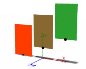
Figure 1
Correct uniform shading
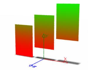
Figure 2
Vertical color blending, refer to shader listing 1
RSL
|
IntroductionThis tutorial addresses some issues relating to the shading of surfaces based on their position in world-space, in particular, their height above the origin of the world coordinate system. For example, a shader may be required to tint the leaves of a tree based on their height above the ground. A model of a tree might consist of several hundreds of leaves, consequently, it would be beneficial to have a single instance of a shader control the shading of the entire canopy of leaves. Modeling & ColorationSince colors can be specified in rib file (or rib stream) why not assign a color to each leaf when it is modeled? For example, the snippet of rib shown below assigns a color to a polygon that represents a single leaf. AttributeBegin
Attribute "identifier" "string name" ["leaf45"]
Translate 0 2 0
Color 0.772 0.964 0.772...
Polygon ...
AttributeEnd
Typically, a model of a canopy of leaves would be baked as a rib
archive.
A shader assigned to the canopy would have access to the color of each leaf via
the Shaders & ColorationA more flexible approach is to postpone all decisions about coloration until a scene is shaded. Figures 1 and 2 show three polygons distributed along the x-axis of world-space. In figure 1 the local origin of each polygon is marked by small black spheres. |
|
|
|
|
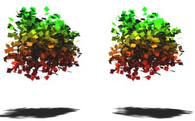
In general it is assumed the shaders developed in this tutorial should apply a constant
colorization to the surface(s) to which they are assigned - figure 1. Applying
coloration based on the height of the micro-polygon
being shaded will produce vertical color blending that, under some circumstances,
may be undesireable - figure 2.
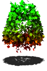
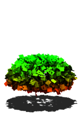
However, as shown in figures 3a and 3b, when the polygons representing the leaves
are small the effect of vertically blended coloration caused by taking the height
of |
|
|
|
Left: coloration by the height of the polygon origin. |
Coloration by Micro-Polygon Height
Listing 1 demonstrates a method of assigning a color to Listing 1 - colorByP.sl
For convenience, the shader uses the //float blend = smoothstep(minheight, maxheight, p[1]);
float blend = 1;
if(p[1] > minheight && p[1] < maxheight)
blend = (p[1] - minheight) / (maxheight - minheight);
else if(p[1] <= minheight)
blend = 0;
For simplicity the shader does not perform any lighting calculations. |
Coloration by Surface OriginListing 2 demonstrates a method of obtaining the height of the local origin of a surface above the origin of the world coordinate system. A modified version of this shader was used to render figure 3a. Listing 2 - colorByObjOrigin.sl
|
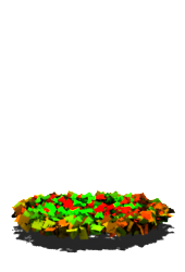
Coloration by User AttributeListing 3 demonstrates a method of coloring a surface based on a user attribute called "position". The values of the attribute represent either the initial or the current (animated) position of a surface. Basing the coloration of a surface on its initial position will ensure its color does not change during an animation - figure 5. TransformBegin
Attribute "identifier" "string name" ["leaf90"]
Attribute "user" "point position" [0.074 -0.130 0.218]
Transform [....]
Polygon ...
TransformEnd
Listing 3 - colorByAttribute.sl
|
Animation & Other Issues
Of the three shading techniques presented in this tutorial
only the |
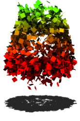
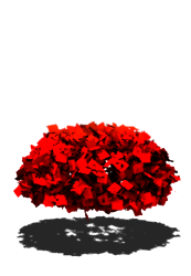
 Figure 4 |
|
Rendered with the colorByP shader. The same effect is observed when the colorByObjOrigin is used. |
|
|
|
Although the |
Using a Procedural Primitive to Generate Polygons
The polygon models used in this tutorial were generated as procedural
primitives using the (helper app) python script shown in listing 4. For
information about helper apps refer to the tutorial
"RenderMan Procedural Primitives".
A sample rib file that makes use of the helper app is shown in listing 5. If the
reader is using the Cutter text editor the |
|
Listing 4 - canopy.py
|
|
Listing 5 - test_canopy.rib
|
|
To render the shadow texture for the
The single parameter, shown below in red, tells the helper app Procedural "RunProgram" ["python canopy.py" "2.0"]
to generate 2000 small polygons. If the reader is
using MacOSX, or Linux, the call to Procedural "RunProgram" ["/usr/bin/python canopy.py" "2.0"] |
© 2002- Malcolm Kesson. All rights reserved.