RfM
RiMel - WyvillEdges


return to main index

Related Tutorial:
    OSL: Wyvill Lines

Download:
    wyvillEdges.zip


Figure 1


Introduction

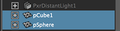
This tutorial presents four scripts that implement an interface that enable the edges of a polygonal object to control the displacement of another object - either polygonal or nurbs. The OSL shader used to achieve this effect is presented in the tutorial OSL: Wyvill Lines.

The interfaces of the custom UI assigned to the shape node of the controlling geometry and to the shape whose displacement is being controlled are shown below.
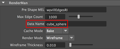


Figure 2
wyvillEdgesUI - control object
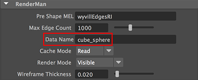


Figure 3
wyvillEdgesUI - controlled object


Important Note: Max Edge Count

Changes to the Max Edge Count must be sync'd on both the control object and the controlled object(s). For example, changing the max count to, say, a 2000 will require a recompilation of the WyvillLines.osl shader after it's macro MAX_VERTICES has been updated (line 32) ie.

    #define MAX_VERTICES 4000

Notice the MAX_VERTICES is twice the Max Edge Count.


Step 1 - Installing the Scripts

It is assumed the reader has followed the recommendations on customizing RenderMan for Maya presented in the tutorial, "RfM: Customizing".

Download and unzip wyvillEdges.zip.
Move,
    getEdges.mel to your maya/scripts directory.
Move,
    wyvillEdges.rman,
    wyvillEdgesUI.mel, and
    wyvillEdgesRI.mel to your maya/projects/RfM_mel directory.
Move,
    WyvillLines.osl to your maya/projects/RfM_osl/src directory.
    WyvillLines.oso to your maya/projects/RfM_osl directory.


Step 2 - Using the Scripts

Launch Maya and check the RenderMan_for_Maya plugin is loaded.

Setting up the Controller Object
    - create a polygonal cube (1x1x1 divisions),
    - deselect, then re-select the geometry,
    - execute the following mel command wyvillEdgesUI();
    - toggle the transform and shape tabs in the attribute editor,
    - change "Cache Mode" to Bake,
    - change "Render Mode" to Wireframe.
The interface, figure 2, should appear in the shape tab of the cube. Assign an instance of PxrSurface to the cube.

Setting up the Controlled Object
    - create a nurbs or polygonal sphere,
    - deselect, then re-select the geometry,
    - execute the following mel command wyvillEdgesUI();
    - toggle the transform and shape tabs in the attribute editor,
    - change "Cache Mode" to Read,
    - change "Render Mode" to Visible.
The interface, figure 3, should appear in the shape tab of the sphere. Assign another instance of PxrSurface to the sphere.


Step 3 - Shading

The WyvillLines OSL shader need only be used on the controlled object - the sphere. The shading network is shown next.


Figure 4


Notice in figures 2 and 3 the "Data Name" must be identical for the controller and controlled objects.


Step 4 - Rendering

Set the project and save the scene.
Open the Outliner and check the controller cube appears before the controlled sphere.


Figure 5


When the scene is rendered two rib archives will be saved in the project's data directory. For example,

    maya/projects/wyvill/data/cube_sphere_attributes.0001.rib
    maya/projects/wyvill/data/cube_sphere_wireframe.0001.rib

The first archive defines two custom attributes while the second rib file defines the geometry that represents a wireframe version of the controller polygonal object. The vertices of the controller object can be animated. However, change the "Evaluation" mode in Maya's Preferences Settings/Animation to DG. The "Render Mode" of the control object can be set to Invisible, in which case the second rib file will not be generated.


Figure 6


© 2002- Malcolm Kesson. All rights reserved.